Since the 2nd Village Telco Workshop in July we have been working on the Beta release of the Mesh Potatoes. Progress slowed immediately after the workshop – I think we all needed a break and some time to organise the resources (e.g. test equipment, prototype manufacture and people) required for the next phase of the project. However we are back in the thick of it now.
The Mesh Potato is a mix of many different technologies: embedded Linux, telephony hardware, VOIP and Wifi. The Radio Frequency (RF) side of the Mesh Potato is a loose end we need to tie up. Unfortunately, data on the RF side is nearly impossible to obtain. To get the full support package from Atheros costs USD$100k. That is beyond our budget and sits uncomfortably with the open source nature of the Village Telco project.
Each AR2317 chip is a little different and consequently each chips requires individual RF calibration on the production line. This calibration ensures each AR2317 product has uniform transmit power and meets certain performance criteria. The calibration data is stored at the end of the SPI flash chip and loaded by the WiFi driver at boot time. Calibration is performed on the production line using a bunch of expensive RF test equipment connected via GPIB to a host computer running special software.
The calibration procedure and most of the data relating to the AR2317 RF section is part of the Atheros “secret sauce”.
On our prototype Mesh Potatoes we were lucky enough to have the WiFi fire up first time. We just copied the calibration data from another AR2317 based product as a starting point. The Wifi worked, but without calibration Wifi performance is likely to be poor. As we had no RF test equipment our visibility was limited – it was hard to even measure the RF performance.
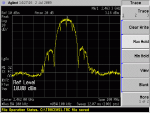
Elektra managed to hook a V1.0 MP01 up to a borrowed spectrum analyser, thanks to kind guys at the CSIR in South Africa. A spectrum analyser graphs the power at each frequency. Here is what the spectrum of a calibrated DIR-300 looks like:

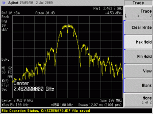
And here is the output from our uncalibrated V1.0 Mesh Potato:

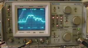
So after the 2nd Village Telco workshop we decided to tackle Calibration. Fortunately, our friends at Atcom found some friends in Shenzhen who have the production line equipment for AR2317 calibration. Here in Adelaide I bought some basic test equipment – an old Tek 492 spectrum analyser from e-bay and a frequency counter. The Tek 492 is an analogue spectrum analyser (with some digital storage ability) from the early 1980’s. In their day they cost $30,000 but are available 2nd hand for around $2,000. Microwave hacking on a budget! The following photo is courtesy of Ben (see below):

In early October we made our first attempt at calibration on one the V1.1 Betas. The automatic test equipment in Shenzhen “failed” us. There were several bugs including low output power (10dB down) and a large frequency offset (60ppm instead of 20ppm). Another concern was that several Mesh Potatoes tested gave different results. Great. Just what we need when we are trying to get 100 Betas out the door for eager developers.
Thus began a two week frenzy of RF debugging, with Mesh Potatoes being couriered back and forth between Shenzhen and Adelaide and much soldering of tiny 0402 size parts under the microscope. These parts appear the size of a small crumb to the naked eye (about 1mm by 0.4mm), but surprisingly you can hand solder them under a microscope with a little patience.
None of the core team are experienced in Wifi or 2.4GHz RF, and we are working without 95% of the data and test equipment we need for proper RF development. So we had a few challenges.
After about two weeks of hard work we made some progress. I managed to bring 3 out of 4 betas up to our target power of 17dBm (the 4th I blew up accidentally). We discovered some areas where the PCB layout could be improved to get even more power (perhaps 20dBm) out of the MP. The system clock was a few kHz off 40.0 MHz which when multiplied up to 2.4 GHz caused the 60 ppm frequency offset. This was actually the largest problem – it caused packet errors at the low data rates which messed up long range performance. Once this was fixed the packet error rate performance started to look as good as the reference DIR-300 unit we were testing against.
The variable power output of different MPs had a simple reason – some of the tiny 0402 parts were loaded in the wrong place. This is very easy to do as the parts have no writing on them. I only spotted this when I noticed two parts with the same value looked slightly different in colour. Usually all parts from the same reel look identical.
With our new-found experience, Atcom decided to make another revision of the PCB (V1.2) to tighten up the RF side. That should be ready for testing in November. If calibration checks out on V1.2 we will then kick off a Beta run.
Given our lack of RF experience, lack of AR2317 data, lack of support from the chip vendor, and very basic test equipment I feel pretty happy with our progress in RF performance over those two hard weeks. The %$%^ Asterisk channel driver for the Mesh Potato took me three weeks to get stable and I am meant to know something about Asterisk driver development!
As well at the core team of Elektra, myself, the Atcom team (Edwin, Alen, Mr. Lee, Peter), their Shenzhen friends and of course Steve, we had some help from Jeff (our RF consultant) and two other people who were especially kind:
I found Ben Johnson while looking for information on the Tek 492. Ben had posted a page on how he repaired his Tek 492. I emailed Ben to ask if he thought it was suitable for Wifi. Ben was kind enough to actually test his Tek 492 on some Wifi signals and email me the results! This gave me the confidence to bid for a used 492 on ebay here in Australia.
I met Dieter through an article I published on Low cost Electric Cars in Renew magazine. He just happened to email me on a day I was messing with the Tek 492 and I found out he was a microwave engineer working in Melbourne. Throughout the RF debugging process Dieter emailed me virtually every day and gave much needed advice and moral support. He even sent over some semi-rigid RF cable with an N-connector to help with the testing.
The Internet is amazing place. I am constantly bowled over by the kindness of people – especially when you are working on open projects.
Links
[1] Measuring Wifi Transmit Power – An in-depth look on how I used the Tek 492 to measure Wifi transmit power.