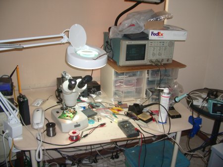
Since my previous post I have been stuck in “boot loader hell” for 3 days! On day 1 I placed the ap61.rom file and had the MP boot loader working but flash support was missing. So i took the redboot-ap61 code that Elektra had prepared and tried to flash it. Clunk – a dead Potato. Nothing from the RS232 serial and no signs of life.

So I carefully retraced my steps and tried to re-flash the MP from JTAG. Still dead. Huh? There followed several days of futzing about, looking at the jtagspi code, trying this, trying that, and getting more and more confused and not a little upset! I just didn’t make sense – if ap61.rom worked the first time why not now?
On Friday morning I took Elektra’s advice and had a break for a few hours, pedaling my bike into town and back. This cleared my head a bit and I tried a new tack. Prior to receiving the first MP, I had practiced flashing an AR2317 design using an off the shelf DIR-300. So I tried this again and no probs – the ap61.rom code fired straight up on the DIR-300. This told me my flashing procedure and the ap61.rom code was OK.
Then I noticed something funny in the ap61.rom boot log from the DIR-300:
a) RedBoot(tm) bootstrap and debug environment [ROMRAM]

production release, version "2.1.3" - built 18:43:19, Sep 20 2007
compared to the first, miraculous boot of the MP01 on Monday:
b) RedBoot(tm) bootstrap and debug environment [ROMRAM]

Non-certified release, version UNKNOWN - built 00:32:22, Aug 7 2007
Different dates!
So this idea popped into my head:
1/ What if Alen (from Atcom) had flashed a boot loader before sending me the MP01?
2/ From my records on Monday, and examining the jtagspi code, I know that my write address for my initial MP01 flash on Monday was wrong: 0x1fc00000
The jtagspi software discards the top 8 bits, leaving 0xc00000. Now on a DIR-300 with 4M the top 2 bits get discarded leaving 0x00000, or the first three blocks of flash. As you would expect.
However when I used the same 0x1fc00000 address on a MP01 with 8M flash, I you get 400000, or half way through the 8M flash. So on Monday I think I flashed ap61.rom half way through the 8M flash.
When I booted, it ran code from the first 3 sectors, which was whatever was in the SPI flash before I flashed it!
So I checked with Alen, and yes he had programmed the SPI flash chips before soldering! So I had been following a blind alley all week – the idea that ap61.rom boots OK on the MP01!
4/ I continued to chat with Alen via IM. Guess what? The MP01s have 8M flash chips fitted – as that is what the reference design had! That also explains why ap61.rom won’t boot – it was compiled for 16M! The mp01.bin Alen used was set up for a 2M flash/8M ram router. You can even see it in the boot log RAM reports:
MP01:
Board: ap61

RAM: 0x80000000-0x80800000, [0x80040760-0x807f1000] available

FLASH: 0x00000000 - 0x00000001, 0 blocks of 0x00000000 bytes each.

RedBoot>
DIR-300:
Board: DLINK DIR-300

RAM: 0x80000000-0x81000000, [0x80040580-0x80fe1000] available

FLASH: 0xbfc00000 - 0xbfff0000, 64 blocks of 0x00010000 bytes each.
So with my 3 yrs old in tow I ran down to my soldering tools guy and bought some “chip quick”, a special low-melting-point solder than can be used to remove surface mount chips with just an ordinary soldering iron. Here is a 30 second video of how Chip Quick works. It’s actually good fun to use, and the low melting point is very kind to the PCB. It also saved me a couple of days finding some one with proper SM rework tools (it’s Friday afternoon before a long weekend here). No way I wanted to wait until Tuesday to fix this bug!
Now I am pretty geeky, but even I don’t have 16Mbyte SDRAM chips just laying about. So it was time for some open-heart surgery. I removed a 16M flash chip from the “donor” DIR-300, and soldered it onto MP001-001 (the first prototype). I powered up and no power LED – there was a short circuit between 3V3 and GND! Bloody Hell – some days you just can’t win! I looked for the elusive short for one hour then gave up on MP001-001 for now. Instead I turned my attentions to the second prototype, MP01-002. I carefully removed the same precious 16M chip from MP01-001 and soldered it onto MP01-002. No shorts this time. I applied 12V and the boot loader comes alive. YAaaaaayyyy!!
As an encore I tried to get Linux to boot….however I had displeased the Gods of embedded systems this week and it was not to be – the Linux image we use for the DIR-300 is stopping part way. For some reason available memory is reported as 32Mbyte rather than the correct 16MByte. However I am going to work on that problem later – time for a few days break!
