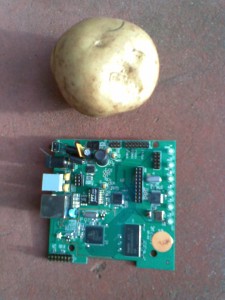
Yesterday (Monday June 1) the courier arrived with the very first Mesh Potato (MP) prototype, which had been hand assembled by the good people at Atcom. This is always an exciting and risky time in the life of any hardware project, as you don’t really know if it’s going to work. In fact, there is a hell of a lot that could go wrong. Like one solder ball under the Atheros BGA chip not soldered, or a nasty PCB or schematic design error that means another re-spin of the PCB and 1 month delay. Or smoke might come out of the Atheros chip when you first apply power. I have seen all of these on past projects…..
Fortunately Alen at Atcom had done some initial tests, like checking for the 3V3 and 1V8 power rails, and making sure the 40 MHz clock was present. So we had some encouraging early signs of life.
My initial goal was to get the boot loader to run – this would prove that most of the AR2317 circuit is OK (CPU, RAM, flash etc). I chose the boot loader image (ap61.rom) that we have been using on the DIR-300 router as this router uses the same Atheros AR2317 chip. So I connected the JTAG cable. The CPU was detected (excellent!) and the jtagspi software started flashing the boot loader. This is a slow process (2.5 hours) using my home-brew JTAG cable, so I headed out for a nice Chinese lunch and a walk with my wife! Alright, so we also went to the bakery and bought a custard filled cake. You need energy to hack.
Two hours later I returned and tentatively connected the RS232 cable and power up the MP. This is what I saw:
No board config data found!
+flash_hwr_init: Unsupported flash device - id=22
FLASH: driver init failed: Driver does not support device
Sorry, FLASH config exceeds available space in FIS directory
Couldn't find valid MAC address for enet0. Using default!
Invalid PHY ID1 for enet0 port0.  Expected 0x0243, read 0xffff
/ar2317-prj/LSDK5.0.2.46/src/redboot_cobra/ecos/packages/devs/eth/mips/ar531x/ccEthernet eth0: MAC address 00:03:7f:e0:02:bf
IP: 0.0.0.0/255.255.255.0, Gateway: 0.0.0.0
Default server: 0.0.0.0

RedBoot(tm) bootstrap and debug environment [ROMRAM]
Non-certified release, version UNKNOWN - built 00:32:22, Aug  7 2007

Copyright (C) 2000, 2001, 2002, 2003, 2004 Red Hat, Inc.

Board: ap61
RAM: 0x80000000-0x80800000, [0x80040760-0x807f1000] available
FLASH: 0x00000000 - 0x00000001, 0 blocks of 0x00000000 bytes each.
RedBoot>
This is actually pretty good – the boot loader is running – with a few complaints about the 8M flash and Ethernet PHY. However a running boot loader means much of the hardware must be OK. Nice.
I have some RedBoot hacking to do (to accommodate the 8M flash and Ethernet PHY) so the next step was to get the Ethernet up. That way I can tftp new boot loader images rather than put up with 2 hour JTAG flash sessions. Actually in hind sight I should have bought a commercial JTAG cable that can flash in 5 seconds. However the Ethernet was dead (no link lights, ping didn’t work), and I didn’t like the look of those complaints about the PHY chip.
So I perused the DP83848I PHY chip data sheet. I decided to probe a few pins on the PHY chip with my oscilloscope to see if it looked alive. One pin I tested was the CLK_OUT pin 25, which should have a 25 MHz signal on it. However it was silent. Hmmmm, not good.
So I contacted Alen via IM and he confirmed that on other designs using that chip p25 definetely had a 25 MHz signal on it. So I checked the second MP01 I had been sent. No CLK_OUT signal either.
When both my MP01’s didn’t have the CLK_OUT signal I suspected it was a wiring/design error. Well, it was just a guess really. Telling these bug hunt stories in review it looks like the outcome was pre-ordained. However at the time you are never really sure. You usually go down many blind alleys, which results in frustration and lack of sleep shutting brain cells down!
Anyway clocks should usually come straight up without any software initialization. So I just checked the reset/interrupt lines (in case the chip was being held in the reset state), then I checked the various power supply lines to the chip. A-HA! One power supply line (pin 22 AVDD33) was not connected! Via IM Alen then double checked his other designs and confirmed that yes, it was a bug.
When I added a wire to supply 3V3 to pin 22 CLK_OUT came up and the network link light started working. Yayyyyyyy!
There is also a golden rule in hardware (and indeed software) development. Anything you change will have bugs. That PHY was changed from the reference design so it’s a natural source of bugs. A bug “emitter” if you like.
Then it was time for some network tests. Ping, and even tftp worked. Very cool. The default state of the PHY chip seems to be just enough to get basic network connectivity. This means I can download new RedBoot images quickly as I modify for thew new flash and PHY.
It was getting late by this stage so I decided to call it a night. So I emailed Elektra about where we were at and went to watch Top Gear which my three year old. However our story does not end there. Elektra was working hard while I was resting and sleeping. When I woke up this morning she sent me several emails detailing how to set up the RedBoot development environment. This is great – saves me a mornings work. Amazing how working 12 hours apart (Berlin and Adelaide, Australia) can be helpful!
Right. Time for some a fresh cup of coffee and some RedBoot hacking.
