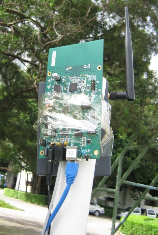
The V1.3 (production) Mesh Potatoes has an etched (PCB) antennas. This post talks about how we tested this antenna and verified the V1.3 design.
Testing at Atcom in June
In June I was visiting Atcom in Shenzhen, China. The first 1.3’s were calibrated and ready for testing so we headed out to a nearby open area with some MP01 V1.2 and V1.3 prototypes.
We taped a V1.2 and a V1.3 back to back on a length of PVC pipe to compare results at roughly the same height. Lead-acid batteries were used for portable power.
We did some A-B comparison tests, e.g. a V1.3 to V1.3 call then a V1.3 to V1.2 call and V1.2 to V1.2 call. As well as making calls we measured the rx signal strength using the node_tune.sh script. We wandered about and tested at various ranges.
Edwin and Alen seemed happy that the two antennas (V1.2 omni and V1.3 printed antenna) worked about the same. This is consistent with the tests Jeff and I performed last December.
The node_tune.sh script reports rx signal strengths to a laptop. It’s hard to be precise as the levels bounce around by several dB. Also we must remember the signal strength indicator on a AR2317 SoC is not a calibrated instrument, it’s just a rough estimate. Typical result might be -70 +/- 3 dBm over 10 signal strength samples. As near as we could tell, the results were about the same for the V1.2 and V1.3.
Given it was an inner city site there were other networks on the same channel so ping times bounced about a bit. Despite that the guys managed to make OK phone calls up to about 350m, with the V1.3 only a few metres above the ground. At that height 350m between omni antennas is actually better than I have achieved in Dili or Adelaide. Not bad considering we were in the middle of a city of 12M people.
Time to introduce some of the Atcom guys. From the left we have Nick and HeZhong. Alen (the MP01 hardware engineer) is in the blue shirt, and Edwin is on the far right holding the potato stick.
It was about 30C and 95% humidity but still nice to be outside. Everyone seemed to enjoy themselves, and it was good training for Atcom in antenna testing. For example when we walked behind a tree the phone call dropped right out, a few steps to one side and the call came back up. I have also used the “potato on a stick” training method with great success in East Timor. Quick and fun education in Wifi propagation.
Testing on the Jetty
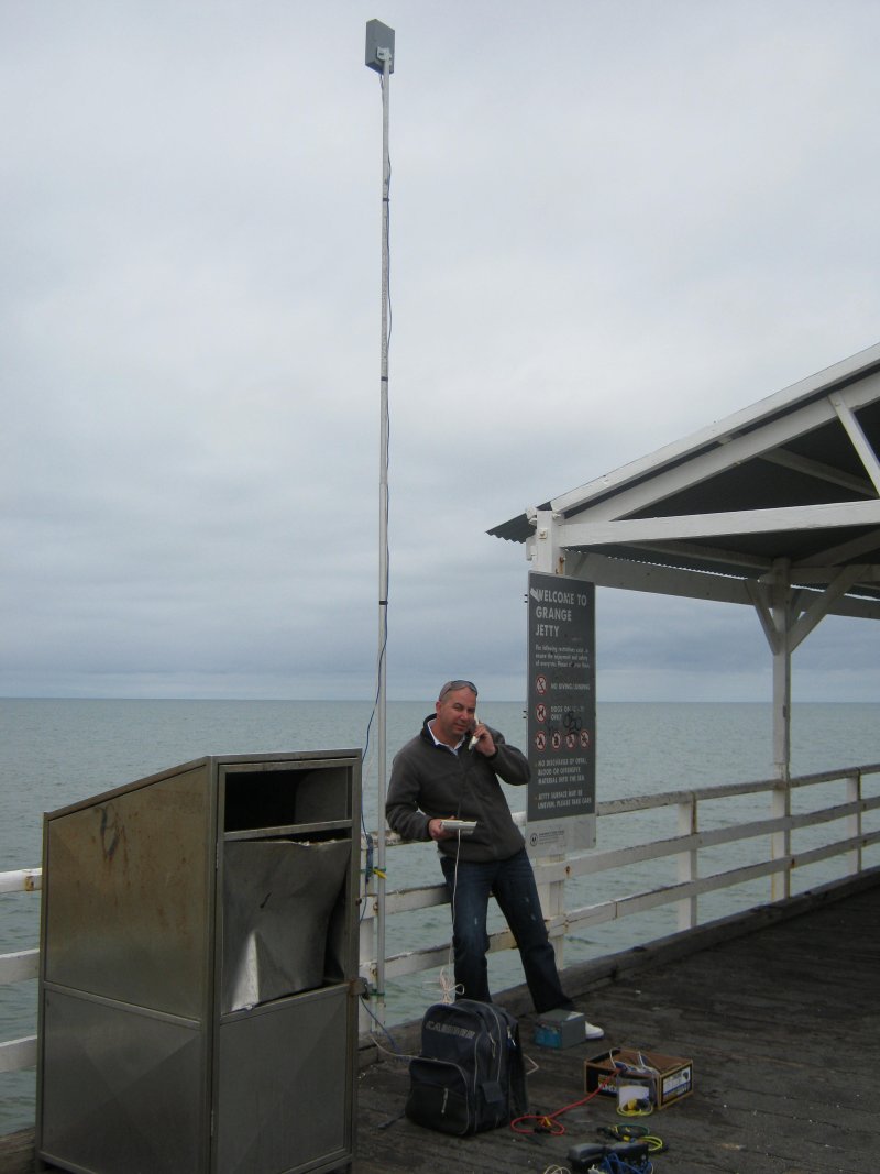
By July I was back in Adelaide. Time for some more potato testing. Joel and I repeated the tests on the Jetty with the V1.3. The site and path (400m Line of Site) was the same as the January tests.
The call quality was fine with the MP in any orientation (I rotated it during a call), even kicking it around on the surface of the jetty with my feet. Pretty similar to January’s results with the prototype PCB antennas. The audio would drop out when Joel stepped in front of his MP but seemed to come back up after a few seconds. Perhaps the Wifi bit rate automatically dropped to account for the extra path loss of Joel!
Checking the Antenna Impedance
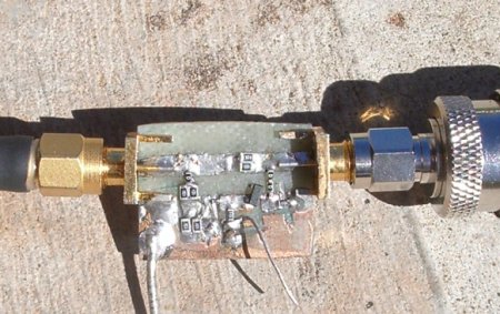
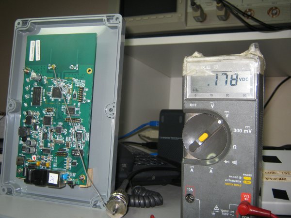
Next I hooked up my Standing Wave Ratio (SWR) bridge to the MP V1.3 antenna. The SWR bridge is described in this earlier post.
The SWR bridge lets me test if an antenna is resonant. If it is resonant the antenna impedance will look like a 50 ohm load at 2.4GHz. The SWR bridge can also be used to compare the V1.3 PCB antenna with other Wifi antennas. As described in the earlier post the SWR bridge produces a DC voltage that indicates the mis-match in the antenna impedance from the desired 50 ohms. A low voltage from the SWR head is a good result. Here are the results:
| Load | SWR Bridge Output (VDC) |
|---|---|
| 50 ohm resistive dummy load | 0.24 |
| open circuit (no antenna) | 0.80 |
| N-type antenna as used on V1.2 | 0.36 |
| Off the shelf router antenna | 0.35 |
| Prototype 17mm PCB antenna | 0.30 |
| Prototype 20mm PCB antenna | 0.40 |
| MP V1.3 PCB antenna | 0.22 |
The MP V1.3 PCB antenna is very close to the “ideal” 50 ohm resistive load. Although with this rough home-made kit a fairer conclusion is that the V1.3 antenna is in the same ball park as the others.
The SWR head & V1.3 antenna was driven from another Mesh potato sending ping floods. A 2.4GHz signal generator would make this testing easier. Using a Wifi transmitter as a signal source means bursty TX signals which makes these measurements tricky. A 2.4GHz sig-gen I could sweep (even manually) would also be great to determine exactly where the antenna is resonant.
MP01 Antenna Options
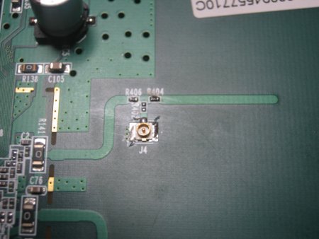
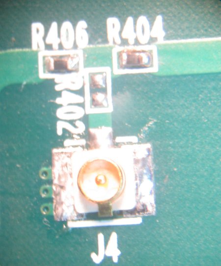
The V1.3 has a group of three 0-ohm resistors that can be used to change the antenna configuration. The resistors simply act as shorting links, they could be replaced by blobs of solder:
The normal configuration is R406 and R404 loaded. This connects the AR2317 SoC to the PCB antenna. To use an external antenna, R406 and R402 is loaded. This connects the AR2317 to J4, where a pigtail can be used to connect J4 to the external antenna.
A third possibility is R402 and R404 loaded. This removes the AR2317 from the circuit, and allows the PCB antenna to be connected to J4 for testing. This is the configuration I used for testing with the SWR bridge in the photo above.
A 2.1km Test between Jetties
On 3 August we made phone calls over a 2.1km path using two V1.3 MP01s with the built in omnidirectional PCB antenna. The phone calls were of excellent quality (no pops or clicks).
Thanks very much to my friend Angelo (a local Electronic Engineer) who helped out on the day. These tests take hours to set and perform and it’s great to have a friend to help.
Angelo is an IT Sys Admin by day and loves trouble shooting. During the Wifi test set up we (quite accidentally) stumbled across a previously unknown but serious bug in the Power over telephone Line (PoTL) part of the power supply. Just in time to prevent the bug being repeated 500 times in the first production run! Thanks Angelo for helping us track this bug down.
For the Wifi tests we used two local jetties (Grange and Henley) which extend 500m out to sea. This reduces interference from nearby Wifi networks and gives good height above ground (sea) level.
Below is Grange Jetty as viewed from Henly Jetty. Sorry about the grainy image below. Grange Jetty is so distant it is hard to image with the camera I have. Angelo is the guy with the brown eyes standing just behind the canopy at the end of the jetty.
Angelo suggested we could have gone much further. I think I agree, as doubling the distance again is a only a further 6dB power loss. But we have run out of convenient jetties for now.
These results, like the earlier results above, show that the V1.3 PCB antenna is working very well. I would like to take this opportunity to thank Jeff Wojtiuk for doing an excellent job in designing this antenna. Thanks Jeff! I would also like to thank Alen Chen from Atcom who has done a fine job on the PCB layout and hardware engineering for the MP01.
Some test data and results, gathered from the Henley end of the link:
- Height at Grange Jetty was 8m+4m mast
- Height at Henley Jetty was 8m+2m mast
- ping -s 1400 -c 100 21% loss 29/42/76 ms
- ping -c 100 7% loss 3/6/12 ms
- Batman metric 240-250
- “iwlist ath0 scan” detected 6 networks, between -81 and -95dBm
I used the node_tune.sh script to measure received signal strength while rotating the Henley end MP01. The signal strength varied between -90 and -86dBm over 360 degrees, with a peak (-86) being reached with the front of the MP01 at 90 degrees to Grange Jetty, i.e. the PCB antenna was edge on. This is an unexpected result.
We tried rotating the MP01 at the Grange end. In this case the maximum signal strength was reached with the MP01 facing Henley jetty. This is the expected result. The difference between the two sites makes me wonder of other factors were involved. For example multipath due to reflections from the sea or nearby metal objects.
Rotating could also have induced a Wifi bit rate rate shift (e.g. from 5.5 to 1 Mbit/s). The AR2317 transmit power varies betwen 15 and 20dBm between 54 and 1 Mbit/s. A rate shift over the link would cause lower lower tx and hence rx power but a higher bit rate. I performed the rotation tests during a regular phone call. Perhaps using broadcast packets would have been a better idea, IIRC they are transmitted at a fixed bit rate and hence fixed power level.
It is important to remember that the AR2317 RSSI indicator is not a calibrated measuring instrument. It is probably not very logarithmic, and no doubt drifts all over the place with temperature and varies from unit to unit. Burst Wifi and interfering signals make power measurements difficult. So we can treat the received signal levels as indicative only. For example I assume an error of +/- 3dB on any RSSI measurements in this system. A much better way to measure RX signal power is to use a spectrum analyser as the receiver.
Using a Wifi calculator I checked the free space path loss and Fresnel zone clearance. The expected power at the receiver is:
Pr = Tx power + Tx antenna gain – path loss + Rx antenna gain
Plugging in the numbers we get:
Pr = 17 + 2 – 106 + 2 = -85dBm
The driver reported the received power as -86dBm, which is a reasonable match if you trust the received power measurement (which I don’t). Still, it’s fair to say we are in the ball park, and that both the antenna and MP01 radio are performing well. Crystal clear VOIP over a 2100m Wifi link with just Omni antennas and 50-100mW is an exceptional result.
I plugged in 17dBm for the tx power above as I was unsure of the bit rate, unfortunately I don’t know how to read the current bit rate of the Wifi driver in ad-hoc mode. The actual tx power could be between 15 and 20dBm, depending on the bit rate.
The 1st Fresnel zone was 8m which we should clear OK with our masts and the jetty height above sea level. However I am not sure what effect the sea has on Wifi. Being slightly conductive it’s probably more reflective than a path over land.
These results show us how important interference and Line of sight (LOS) are to Wifi. In Dili we couldn’t set up a 300m link between MPs equipped with Omni-directional antennas due to massive interference. Even to obtain that range with directional antennas we needed huge, free standing masts (up to 25m) to clear obstacles like trees. However “on the beach” we can achieve an impressive 2.1km with omnidirectional antennas and modest power levels.
Links
Coincidentally a couple of friends sent me this link on PCB antenna design while I was writing this post.
